
|
Projects Lithium Ion Battery Smart Charging System The next logical step after building a Lithium ion battery management system would be to build a compatible charging system, so, this is it! |


| |
|
|
||
|
|
|||
| |
|
|
|
|
|
|
|
|||
|
|
|
|||
|
|
|
|||
|
|
|
|||
|
|
|
|||
| |
|
|||
|
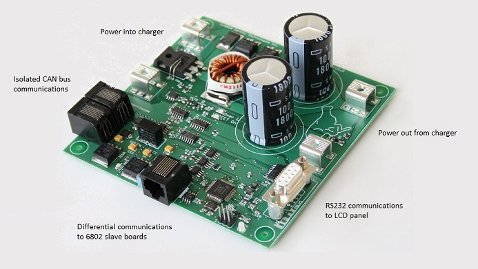
Overview: The smart charger hardware, firmware and communications were built with the following specifications
The
above picture shows the main smart charger board. I ended up
taking a fair bit of the BMS board and incorporating it into the
charger electronics so that it could function in a number of different
configurations.
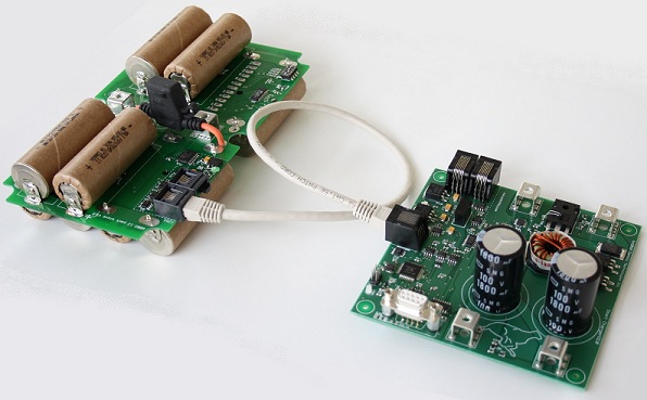
The smart charger uses the same
method of differential communications so it can communicate directly
with the Linear LTC6802 boards in a daisy chained fashion. One
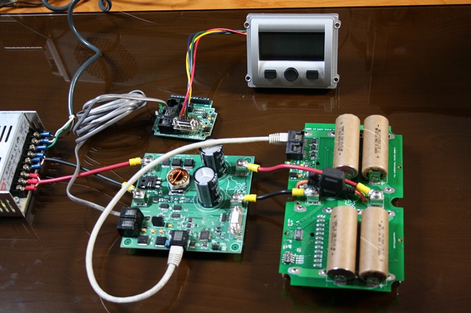
board is shown here but a maximum of 16 could be used. 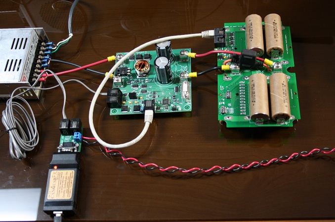 This is a complete, working setup
with power coming from a DC power supply (left) and flowing through the
smart charger. The CAN-4-USB/FX interface is connected to a PC
that is running configuration and monitoring software. The DC
input can be up to 75 volts but can be throttled back to charge a
single cell if needed. The 12 cell pack shown will have a final
charge voltage of 50.4 volts. There are a number of isolation
points in this system. The CAN bus, and therefore the PC, are
isolated and the 6802 communications are isolated as well. This
means the CAN bus ground, the power supply ground and the 6802
communications bus ground are all isolated.
In this configuration the smart charger is taking its commands from the BMS. If you haven't already looked, you can see all the features of the BMS board here 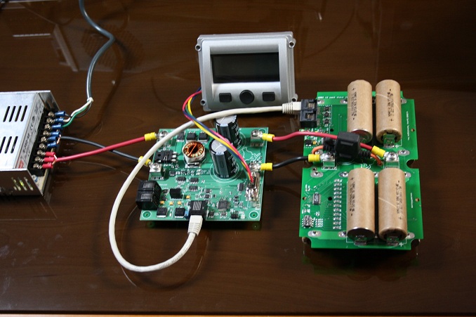 Yet another configuration would be to have the smart charger work in a stand along mode and have charging information and simple configuration choices displayed on the LCD screen. |
||
|
|
Zanthic Technologies Inc. |